Menu
Menu
Website by ThierryD
rienquepourlesyeux@free.fr
Copyright 2010-2015
All rights reserved
Reproduction prohibited
Last update : 2021/03/11
In this article, I propose to make a lightning detector for DSLR camera,
or thunderstorm detection DSLR camera for less than 10 Euros.
It is more exactly a shock sensor.
Lightning is an event lasting a few hundred milliseconds,
it was impossible to detect lightning by noise that propagates at a speed
well below that of light (about 300 meters / second for noise).
Another solution might be to detect the light from the flash, but the light is emitted
when lightning is visible. By the time the electronic circuitry detects the light
make the relay and from the camera triggers the reflex camera, there was a
unlikely to photograph lightning.
Best solution is to detect the electric discharge that occurs in the cloud
So a few tens of milliseconds before the light of lightning appears.
The discharge in the cloud produces radio waves, radio waves is such that it will detect.
The first wave is that of the tracer. The tracer is the ionization of air (a small electric arc)
before the true and powerful discharge (lightning that we see). this will even take pictures of lightning
during training, following the exposure time set on the camera for the photo and the luck factor.
The flashes are not predictable in duration, power (under or over exposure) and direction.
The most simple and quickest way is to use a simple radio receiver, an old radio will be very
the trick (photo01 and photo02). For my part I use a portable FM / AM (photo02).
This radio will be paid on AM (LW - Lower Wave or MW - Medium Wave) because what we want to capture or play
is a crash that occurs on medium and low frequencies (about 150-2000 KHz is fine).
This does not work on an FM receiver for several reasons: too high frequencies (100 MHz), congestion
the frequency band limitation of the scope FM (about 30 Kms).
AM frequencies are congested can (fewer and fewer stations), correspond to the radio wave that is desired
detect and have a range exceeding 100 kms.
The easiest way is to use a radio receiver AM (LW - Lower Wave or MW - Medium Wave) that has a headphone output,
but you can also connect directly to the speaker of the receiver without any problem.
The photo03 (and Photo08) shows the electronic circuitry to realize that we can divide into 3 parts.
This assembly is powered by a DC voltage of 12 volts but it is also possible to feed into 9 volts.
The first part revolves around an operational amplifier (the TLO081 or LF351), this integrated circuit can cause
a rising edge at its output when the signal received from the radio receiver exceeds a certain threshold that is adjusted with
47 Kohm potentiometer. This level of detection is very close to that of the detector drops of water.
There is still a big difference is the presence of 47µF capacitor which serves to isolate the output voltage
radio receiver, which is an audio signal, the DC voltage of Vcc / 2 (Vcc / 2 = feeding 12 volts divided by 2)
that we created with the two resistors 10Kohms (Electronics we call it a bridge divider).
For information, you can, in this first part, replace the three resistors of 10 Kohm and
47 Kohms potentiometer and the 2,2 Kohm, by 3 resistors of 1 Kohm and a potentiometer of 2,2 Kohm.
47 Kohm potentiometer is used to adjust the threshold, the 2.2 Kohm fine adjustment
The second part consists of two switching diodes 1N4148, 100µF capacitor
and resistance of 330 ohms is a delay of approximately one second.
This delay serves to maintain the state of detection and allow time for your SLR camera trigger.
It also serves to eliminate interference detection, because many landfills may occur in the cloud before the flash.
The third part is just insulation between the mounting and your SLR, it is composed of an NPN transistor
(Type 2N2222) and a relay (coil with the 1N4004 diode on the right of photo03).
This role will be to relay to a contact, as will a wired remote.
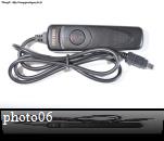
Besides connecting the mounting my Nikon D90, I bought on Ebay not too expensive (11 Euros) a remote control (photo06)
I have disassembled the socket and the pin contacts (photo07). So instead it's my finger that makes
the contact button on the remote control, relay the fact that in my place.
On photo07, we can see that the remote for the Nikon D90 is composed of two bimetallic, one for development,
the other for the outbreak of the photo. Our relay will then make a contact between the blade as the development of welded
the blade trigger, and the blade common to both bimetal.
For this part, I could give you any other information as the plug and pin depends
the model of your SLR. The easiest way is to do like me and therefore to buy a wired controller.
I also added a LED and a resistor of 1 Kohm just to have a light when lightning is detected.
The photo04 shows the electronic assembly placed in a small box, the box connected to the photo05 AM radio receiver.
To observers, you will notice that there 3 capacitors (photo04) while on my diagram (photo03) there are only two.
I just added a 100µF capacitor between 12 volts and ground to filter the noise because the power
12 Volt is external to the housing.
The use of electronic assembly is very simple:
Set the radio to an unused frequency (or a place you do not hear music or words,
just background noise, the noise Pfffffffffff ...), famous for my part I set the receiver to 1600 kHz AM (photo02).
Connect the headphone output of the AM radio receiver or the speaker output to the input of electronic assembly.
Turn the 47 Kohm potentiometer for the relay does more contact and the LED is extinguished.
The 47 Kohm potentiometer adjusts the sensitivity of detection assembly and the 2,2 Kohm for fine sensibility.
To make the editing very sensitive, slowly turn potentiometer until the LED turns off.
If the assembly is very sensitive, it will detect even the press a switch your home's electrical storms but also
detect several tens of kilometers. If the storm is very close to you, turn the knob a little after the
extinction of the LED so that assembly less sensitive to interference.
Connect the output relay to your SLR via a cable you inspiring the remote for your SLR.
Set your SLR on manual with an aperture of F5.6, an exposure time of 1 second, the white balance on cloud, the ISO
200 and, of course, the focus on manual that you have previously set to infinity.
This basic setup will allow you to make a first test of the vehicle and check that everything works well.
After it is up to you to find tune your reflex that is what you want to photograph.
You must set your reflex completely manually to accelerate the onset of the picture
otherwise the internal electronics of the reflex may take several tens of milliseconds to find the right settings.
The photo08 is a simplified representation of the electronic assembly.
This will allow, to those who do not know much about electronics, to build the lightning detector.
You can see some pictures I made with this setup in my gallery under "Lightning and thunderstorms.
This arrangement works perfectly (even sometimes too well), it is still a chance factor
for framing and direction of the lightning.
Watch my column "Lightning and thunderstorms" for examples of photos.
Your turn, good hunting ...
For questions, there is a section in the forum.
I added in the "Download" section of this website a ZIP file
(detecteur foudre par jon21 (Lightning Detector by jon21).zip).
This file contains the files of the printed circuit board (PCB) created by Jon21 (very nice user's of the forum).
You will find additional information for the realization of the lightning detector.
For information, he used the following relays: Relais choisi par Jon21
A big thank you to him for that amount.
If you want to see photos of lightning, made ??by him with the lightning detector: Site de Jon21
Photo09 and Photo10, two more pictures to show you the small PCB of the lightning detector.
Photo11, I have included the possibility to detect lightning, either by radio (fastest)
either by a photoresistor for detect the light produced by the lightning.
It is sufficient to use a photoresistor (reference example in E44 : LDR05, price of 0.50 Euros)
and a resistance of 10 Kohms.
This photoresistor can, according to your needs, replace the radio and fix it on the jack.
It will connect on the red wire to +12 V or +9 V to make it work.
The photocell detects a sudden change in brightness (increased light when the light flash).
This detection technique is slower than the radio technical but also works.
A lightning flash lasts 500 ms or even longer, it is quite possible to photograph lightning with this technique.
Copyright 2010 - 2013 ThierryD - http://rienquepourlesyeux.free.fr
Last update 27/08/2013
Reproduction prohibited