Menu
Menu
Website by ThierryD
rienquepourlesyeux@free.fr
Copyright 2010-2015
All rights reserved
Reproduction prohibited
Last update : 2021/03/11
I present here my detector drops of water or other small object
average size in opaque or transparent.
The idea is to use an infrared barrier that will detect the drop
very small objects but also transparent objects like drops of water.
The sensor is powered via a small transformer 12 volts.
The photo01 shows the electronic diagram of the detector, can be divided into 4 parts.
The first part revolves around an operational amplifier (the lf351), this IC allows
cause a falling edge at its output when an object crosses the cut or infrared.
This infrared barrier is composed of an infrared diode (photo05) and an infrared sensor
(The BPW41, photo06). Potientiomètre The 2.2 ohms adjusts the sensitivity (photo04).
This sensitivity is set for each use, as it depends on the ambient light, which
may change if you use natural sunlight for example.
The sensitivity is to adjust when you change the distance between the IR diode and the sensor.
As you can see on the photo03, I mounted the IR diode on a piece of molding electrical
what I used to slide away, more or less the diode sensor which enables the use
This Motag for various objects much larger than the drops of water.
Plus you have made your adjustment near the trigger, the assembly will be more sensitive.
The second part revolves around the famous NE555, integrated circuit, which creates
temporisations.Le of potentiometer 150 ohms (photo04) adjusts the delay time
before tripping. This is necessary because as a rule, the detector will be located outside the
part of the picture the detection has taken place before the object is on it.
The NE555 is a very specific circuit, which will enable us, in the case of drops of water, choose
now we want to photograph (or the time it touches the water, he or she sinks, or
he or she appears). Once the delay setting found, the accuracy will always NE555
capture the same moment throughout the shoot.
The third part is mainly composed of the PNP transistor (a 2N5322 for example), the capacitor
100µF and two switching diodes (type 1N4148) connected in series and to charge the capacitor
when the PNP transistor is conducting. This creates a second timer that does not need to be
very precise but exceed 1 second. This second delay is used to maintain the status detection
and allow time for your SLR camera trigger. Two scenarios may arise:
You have made the development maunuellement, in this case a single pulse is sufficient to trigger the camera.
You have left the development in automatic in this case should be kept to a minimum one second state
detection for your SLR is the time to its development and trigger the shot.
The fourth part is just insulation between the mounting and your reflex is composed of an NPN transistor
(Type 2N2222) and a relay (coil with the 1N4148 diode on the right of photo01).
This role will be to relay to a contact, as will a wired remote.
Besides connecting the mounting my Nikon D90, I bought on Ebay not too expensive (11 Euros) a remote
I have disassembled the socket and the pin contacts. So instead it's my finger that makes
the contact button on the remote control, relay the fact that in my place.
For this part, I could give you any information since the plug and pinout depends
the model of your SLR. The easiest way is to do like me and therefore to buy a wired controller.
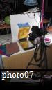
Photos 07 and 08 shows the assembly in use. It is this meeting which allowed me to take pictures
you can see in my gallery under "water games".
Copyright 2010 ThierryD - http://rienquepourlesyeux.free.fr
Last update 04/02/2010
Reproduction prohibited